In this practical project, we will build a monitoring device to monitor the electricity usage of certain electrical devices (we’ll use a power distribution outlet connected to multiple electrical devices to monitor its electrical usage parameters). To monitor these electrical parameters, we will use the Peacefair PZEM-004T V3 energy monitor. The PZEM-004T module is a mains-powered module that measures the voltage, current, power, frequency, and power factor. It provides these values over a serial interface.
Important note
This project involves a direct connection to electrical lines. Please be aware that you’re exposing yourself to electrical hazards that can cause fire or be fatal. If you have no experience in doing this, then you’ll need to seek help from someone who has experience and understands the risks of connecting to electrical lines.
Requirements
You will require the following hardware for this practical exercise:
ESP32 NodeMCU
Peacefair PZEM-004T V3 energy monitor (including a CT transformer)
4-pin 2.54mm pitch wire pin header
Hi-link AC 100-220VAC to DC 3.3V 3W transformer
Electrical wire
You will also need your Arduino IDE ready to upload code and a web browser to open the output.
Now that we have these components, we can wire up the hardware.
Connection diagram
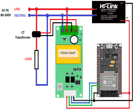
Figure 5.7 shows how we will wire up the hardware:

Figure 5.7 – Wiring diagram for the practical scenario
Now, we can set up the hardware.
Setting up and connecting the hardware
Follow these steps to set everything up for this practical exercise:
For this sketch, you need to download and install some Arduino libraries:
- PZEM-004T V3: https://github.com/mandulaj/PZEM-004T-v30.
- ESP_ASYNC_WIFIMANAGER: https://github.com/me-no-dev/ESPAsyncWebServer/archive/refs/heads/master.zip.
- AsyncElegantOTA: https://github.com/ayushsharma82/AsyncElegantOTA.
Connect the ESP32 NodeMCU to a USB port on your computer.
Download the sketch from https://github.com/PacktPublishing/IoT-Made-Easy-for-Beginners/blob/main/Chapter05/enermo/enermo.ino. Open the code, then compile and upload it while using Node32s as the board. Select the appropriate serial port that appears when you connect the ESP32 board (you can disconnect and reconnect the board to observe the serial port used by ESP32).
Connect the ESP32, PZEM-004T, Hi-Link AC to DC transformer, and CT current transformer (included with PZEM-004T) according to Figure 5.7. Please note that only one cable of the AC that goes to the AC load (such as a lamp or electronic device) should be inserted inside the CT transformer. Be extremely careful when handling the wiring for the AC IN as it can cause electrical hazards or start a fire.
Since the sketch includes Wi-Fi Manager (ESP_ASYNC_WIFIMANAGER), you don’t have to hardcode your Wi-Fi network credentials in the sketch. You can set your Wi-Fi network credentials during the initial stage using your mobile phone or computer. In the initial stage, the ESP32 microcontroller will act as a Wi-Fi access point. From your computer or mobile phone settings, go to your Wi-Fi settings and find the access point created by the ESP32 microcontroller; it will have the name ESP-xxxxxx, where xxxxxx represents the last six hex digits of the ESP32’s microcontroller unique ID. After connecting to the ESP32 access point, you will be automatically redirected to a home screen.
With this, we can now configure the connection of the hardware for the access point.

