In this hands-on project, we’ll build an access control system using an MFRC522 RFID reader connected to an ESP32 microcontroller. This system will read, write, and register MIFARE 13.56 MHz RFID cards. When a scanned ID card matches any registered ID, the microcontroller will issue an MQTT publish message. This message instructs a remote MQTT subscriber, running on another ESP32 microcontroller, to activate the corresponding switch meant to enable door access. However, in this demonstration, we won’t connect to an actual switch. Instead, we’ll illuminate the built-in LED on the MQTT subscriber’s ESP32 microcontroller to simulate the process.
You will require the following materials:
2x ESP32 NodeMCU microcontroller
1x MFRC522 RFID card reader
1x push button (latch) switch
2x MIFARE 13.56 MHz RFID cards, fobs, or NFC cards
Jumper cables
Making the connections
Connect one of the ESP32 NodeMCUs to the MFRC522, as shown in the following diagram:
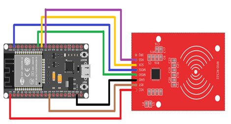
Figure 4.7 – Connection diagram for ESP32 to MFRC522
Let’s take a closer look at the wiring connection between the RFID/NFC MFRC522 module and the ESP32 microcontroller:
| MFRC522 Module | ESP32 |
| SS | GPIO 5 (pin 29) |
| SCK | GPIO 18 (pin 30) |
| MOSI | GPIO 23 (pin 37) |
| MISO | GPIO 19 (pin 31) |
| IRQ | Not connected! |
| GND | GND (38, 32, or 14) |
| RST | GPIO 27 (pin 11) |
| VCC | 3V3 (pin 1) |
Table 4.1 – Connection wirings for ESP32 to MFRC522
Important note
As the pin placement can vary across different MFRC522 modules, please arrange them appropriately with caution. Additionally, we need to connect the push on push off switch to the ESP32 microcontroller. Connect the middle pin to the ground (GND), and the normally open pin to GPIO 32 (pin 7).
From here, we can start implementing the code. As part of this, we need to obtain the necessary MFRC522 library:
In the Arduino IDE, select Sketch, then Include Library, and finally Manage Libraries…:
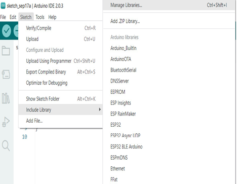
Figure 4.8 – Selecting Manage Libraries… to see the list of libraries
In the LIBRARY MANAGER area, search for mfrc522 and proceed with the installation. With this setup, we are now prepared to explore RFID cards:
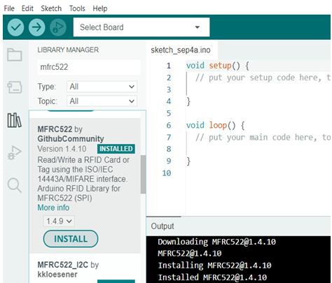
Figure 4.9 – Searching for and installing the MFRC522 library
We can now create an appropriate sketch based on the examples that are within the Arduino IDE:
In the Arduino IDE, click File | Examples | MFRC522 | DumpInfo. The sketch will appear in your Arduino window:
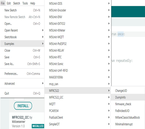
Figure 4.10 – Selecting the DumpInfo example from the MFRC522 library
Find the #define RST_PIN 9 line and change the value to 27 since we’re using GPIO 27 for the RST pin.
Find the #define SS_PIN 10 line and change the value to 5 since we’re using GPIO 5 for the SS pin:
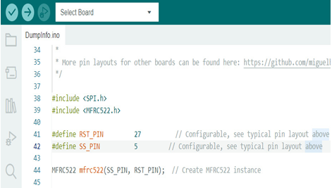
Figure 4.11 – Changing the code for RST_PIN and SS_PIN
Now, it is time to burn the code to your ESP32 microcontroller. Connect the ESP32 microcontroller to the USB port of your PC and choose the board from Tools | Board | ESP32 | Node32S.
Then, choose the port that’s used by the ESP32 microcontroller by clicking Tools | Port; a COM port will appear. Choose the one that appears after you connect the ESP32 microcontroller. For instance, it could be port COM3.
After that, you can check whether the sketch is clear or contains bugs by clicking the button, or directly upload the code to the ESP32 microcontroller by clicking the
button, as can be seen in Figure 4.11. Do not forget that you need to press the EN button to enable it in the programming mode.
Now, we can check the messages that are sent by the ESP32 to see whether the code has been uploaded successfully:
If uploaded successfully, click on Tools | Serial Monitor to see the messages sent by the ESP32 microcontroller.