You may press the RST button on the ESP32 microcontroller (the button other than the EN button) to force the ESP32 microcontroller to reboot so that you can see all the messages from the start.
Next, we’ll learn how to grant access with the RFID tag. As part of this, we need to program the appropriate read, register, and access operations to it:
For this step, we will use an ESP32 microcontroller connected to the MFRC522 module as the RFID reader, register, and verify unit, while employing another ESP32 microcontroller as the remote access switch control. Begin by downloading the ESP32_MQTT_Subscriber.ino sketch from https://github.com/PacktPublishing/IoT-Made-Easy-for-Beginners/blob/main/Chapter04/mqtt_rfid_practical/ESP32_MQTT_Subscriber.ino.
Then, you must modify the Wi-Fi SSID and password so that they match your Wi-Fi access point credentials and choose the MQTT server you’re using (you could use your Raspberry Pi MQTT server, as discussed in Chapter 3, Integrating Application Protocols or an available online MQTT server such as http://mrtg.prcn.bitcoin-analytics.com/).
After making these adjustments, upload the code to the ESP32 microcontroller connected to the MFRC522 module.
Open the Serial Monitor screen to observe the messages. Ensure that the system connects to both Wi-Fi and the Mosquitto server. Initially, position the switch to OFF and place an RFID card on the MFRC522’s read area. Remember, the card must be close as the maximum reading distance (depending on the MFRC522 module) is approximately 10 cm. The RFID card ID should appear; try multiple cards to test the reader function. In read mode, the reader compares the scanned card ID with registered IDs. If the system finds a match, it will send a publish message to the Mosquitto server. However, as no card IDs are currently registered, no publish messages will be sent.
To register a card ID, switch to the ON position. Scan a card again; you should receive a message confirming the card ID registration. Register a few more cards for testing purposes.
Once you have registered the cards, revert the switch to the OFF position and scan a registered card. You should now see a message indicating that the card ID has been published.
At this point, we can work on getting the MRTG message published by the RFID reader. As part of this, we need to work on the necessary wiring:
Connect the ESP32 microcontroller board with the relay module, as shown here:
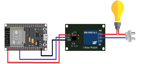
Figure 4.12 – Wire-up diagram for connecting the lamp to the relay outputs
We need to connect a load such as a lamp to the relay outputs.
Download the ESP_MQTT_MFRC522.ino sketch from https://github.com/PacktPublishing/IoT-Made-Easy-for-Beginners/blob/main/Chapter04/mqtt_rfid_practical/ESP_MQTT_MFRC522.ino.
Change the Wi-Fi SSID and password according to your Wi-Fi access point credentials and the MRTG server that you use (you can use your Raspberry Pi MRTG server, as discussed in Chapter 3, Integrating Application Protocols). Alternatively, you can use an available online MRTG server, as mentioned previously.
After changing those variables, upload the code to the ESP32 microcontroller that is connected to the relay module.
Go to the serial monitor and monitor the messages there. Tap an RFID card that is already registered. You should receive a message such as S1 ON; look at the appropriate relay that it is also switched to the ON position.
We can expand the project so that more relays are served. To do this, we can use a web server, where each card ID can be set to have different access to different relays. In the real world, these relays can be used to open doors and gates, switch lamps on/off, control electronic equipment, and more.
In this practical scenario, we have demonstrated how to create an access control system using RFID readers and apply concepts from the protocols we’ve discovered, such as employing Wi-Fi, Bluetooth, and RFID as short- and long-range communication protocols. By following the provided steps, you now understand how these protocols can work together in IoT networks and have gained hands-on experience in implementing a simple IoT communication system.