RPL is a routing protocol that’s used for powering low-power and lossy networks, such as the use cases we have highlighted for IoT networks. It is based on the IPv6 protocol and is designed to be scalable and efficient, allowing it to be used in scenarios where there are many devices with limited resources.
RPL uses a directed acyclic graph to route packets through the network, allowing it to adapt to changes in the network and maintain connectivity, even with oncoming errors or losses that may result. It can also optimize the use of energy and other resources. It can support a wide range of topologies and network configurations, some of which include a single central node or others within more distributed networks with multiple nodes. This flexibility allows it to be used within a myriad of IoT applications.
Next, we will look at some more technologies that are part of popular communication protocols: mesh networking, RFID, Wi-Fi, and Bluetooth.
Mesh networking, RFID, and Bluetooth
Many protocols are yet to be mentioned as part of IoT. Here, we’ll highlight three more to add to your toolkit, with a special emphasis on RFID technologies, given their prevalence within open source and industrial communities.
RFID
RFID technologies are used to identify and track objects through radio waves, and in IoT, they are used to track a wide array of devices or sometimes people. There are two main types of RFID technologies: passive and active. Passive ones use tags that do not have power sources and instead depend on the power transmitted by the reader for them to send their data, while active systems use tags that have power sources and can transmit data over longer distances.
RFID technologies can identify and track objects without necessitating a direct line of sight, making them perfect to use within environments where objects are difficult to track, such as in manufacturing environments or within warehouses. They can provide real-time tracking and location information, which is useful for many industries, such as within supply chains or inventory management. They have the disadvantage of possibly being expensive – particularly for the active RFID systems – and that they can be disrupted by physical barriers such as metal or water, which can affect their accuracy and range.
It is simple to create IoT networks that are based on RFID; they function just as any other sensor would. The RFID reader would simply act as the sensor and pass on the information that it receives from the tag through a gateway, which, in turn, is put through the cloud for storage and further processing.
The following diagram shows one such example of how such an architecture would be positioned:
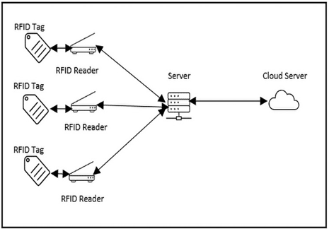
Figure 4.4 – RFID sample architecture
Now that we have a general understanding of how RFID technology works, let’s consider a small practical on building a system based on RFID. We want to be able to activate a certain mechanism when the correct card is presented to the reader.
First, link your ESP32 with the hardware diagram, as shown here:
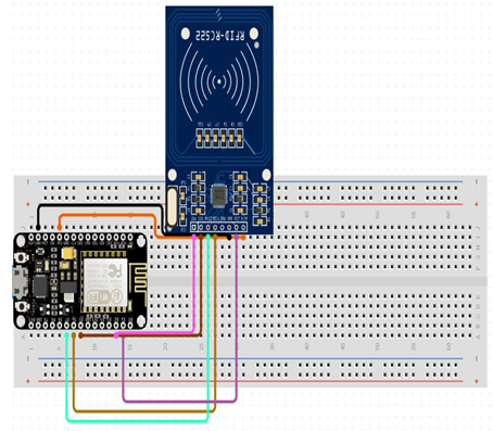
Figure 4.5 – Simple RFID wire-up diagram
Now, we want to program our ESP32 with the following code. Note that the RFID module will be using the SPI protocol to communicate with the ESP32.
First, we want to include the two libraries that we mentioned in the Technical requirements section. The SPI.h library will allow us to establish communication between the RFID module and the ESP32 card, while the MFRC522.h library will allow us to communicate with the module. Have a closer look at these libraries if you want to see what functions they allow us to perform:
#include <SPI.h>
#include <MFRC522.h>
Afterward, we want to declare constants in the form of SS_PIN and RST_PIN:
#define SS_PIN 5
#define RST_PIN 0
Then, we must set the parameter of the IP address, as follows:
const int ipaddress[4] = {103, 97, 67, 25};
Now, we must set the variables that are required as part of the solution. First, we want to initialize all values in nuidPICC to all zeroes. Afterward, we want to initialize a MIFARE_Key variable and create an RFID variable that corresponds to the constants that we have set:
byte nuidPICC[4] = {0, 0, 0, 0};
MFRC522::MIFARE_Key key;
MFRC522 rfid = MFRC522(SS_PIN, RST_PIN);
At this point, we can set up the system. Here, we must initialize the serial USB, where we initialize the RFID with the PCD_Init() command and print out the version of the reader:
void setup() {
Serial.begin(115200);
Serial.println(F(“Initialize System”));
SPI.begin();rfid.PCD_Init();
Serial.print(F(“Reader :”));
rfid.PCD_DumpVersionToSerial();}
As part of the loop section of the code, we must ask the ESP32 to continually read the RFID as we want to check whether there is a card that is being swiped to test whether it is an appropriate card:
void loop() {readRFID();}
Now, we must create a new function to read the RFID card. As part of this, we’ll look for a new card and verify whether the NUID has been read. Then, we can store the NUID in the nuidPICC array that has been created to track the data that has been read from it. At this point, we can print out the RFID UID and its size in decimals, then halt the PICC and stop the PCD from being encrypted:
void readRFID(void) {
for (byte i = 0; i < 6; i++) {key.keyByte[i] = 0xFF;}
if ( ! rfid.PICC_IsNewCardPresent())return;
if ( !rfid.PICC_ReadCardSerial())return;
for (byte i = 0; i < 4; i++) {nuidPICC[i] = rfid.uid.uidByte[i];}
Serial.print(F(“RFID In dec: “));
printDec(rfid.uid.uidByte, rfid.uid.size);
Serial.println();rfid.PICC_HaltA();rfid.PCD_StopCrypto1();}
Afterward, we can use a helper routine to dump a byte array as a hexadecimal value:
void printHex(byte *buffer, byte bufferSize) {
for (byte i = 0; i < bufferSize; i++) {
Serial.print(buffer[i] < 0x10 ? ” 0″ : ” “);
Serial.print(buffer[i], HEX);}}
For the full line of code, check out this chapter’s GitHub folder in this book’s GitHub repository, as mentioned in the Technical requirements section.